Adjusting the clearance of brake shoes (Brake without autofocus) of
Brake Shoe Clearance the Adjustment ( a Non-Automatic Adjuster Tipo)
1- brake with a pair of shoes applicants (duplex)
Composition:
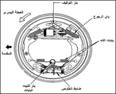
ride calf cylinder in this system as is evident in (1). The shoes are compressed by means of a return spring on the adjusting nut and piston. When the pedal is pressed, the piston is pushed under pressure and the adjusting screw pushes the shoes out until the friction linings come into contact with the circuit.
 |
| Figure 1: Advanced two-shoe brakes |
Wear in the bushings will increase the clearance between the bushings and the circuit. This increases the pedal travel during braking and thus reduces the remaining pedal distance, so a clearance adjustment process must be performed to overcome this.
To perform the adjustment, the adjusting spring must be raised and the adjusting nut turned, as shown in Figure (2). When the nut is turned, the length of the adjusting bolt in contact with the shoe changes and, accordingly, the clearance changes.
 |
| Figure 2: Adjusting the clearance by turning the nut |
The adjusting nut can be rotated by means of a special tool that is inserted through the adjusting hole on the back of the mounting plate.
Adjusting the clearance
a- Carrying the car on the crane, so that the wheel with which the clearance is to be adjusted is free.
b- Release the hold brake.
c – Remove the adjusting hole plug on the mounting plate.
d- Use the special tool (brake adjustment kit), turn the adjusting nut until the wheel stops spinning (check this by trying to turn the wheel by hand).
| CAUTION: To increase the length of the adjusting bolt (reduce the clearance) use the special tool to adjust the clearance, by moving the special tool from the inside out to turn this adjusting nut without regard to the position and location of the wheel. To reduce the length of the adjusting screw (increase the clearance) move the special tool from the outside to the inside as shown in Figure (3). For this reason, the adjusting screw threads were made: a left thread on the left wheels and a right thread on the right wheels. Therefore, care must be taken when installing the adjusting screw and adjusting nut in their correct places (see Figure 4). |
 |
| Figure (3): Adjusting the clearance of shoes |
 |
| Figure (4): Uniform adjustment method for wheels |
C – The special tool is used to turn the adjusting nut back several teeth to obtain the required clearance. The number of teeth that must be returned to obtain the clearance is specified in the specification booklet for each vehicle.
Repeat steps 3-5 for all shoes.
| CAUTION: For a two -cylinder wheel, do not attempt to adjust the two shoes at the same time. |
h- Install the adjusting hole plug.
2- Servo brakes :
Installation:
This type is designed as shown in Figure (5). The upper part of the shoe is pressed against the centerpiece (stop benz) by means of rewind springs. The bottom of the boots is pressed against the clearance adjuster by means of tension springs. The clearance is adjusted by turning the clearance adjuster.
 |
| Figure (5): Servo shoe brakes |
Adjusting the clearance
a- Carrying the car on the crane, so that the wheel with which the clearance is to be adjusted is free.
b- Release the hold brake.
c- Solve for tightening the spring-setting bolt as shown in Figure (6).
 |
| Figure (6): Loosen the spring-setting bolt |
d- Remove the adjusting hole plug on the back of the mounting plate.
C – Move the sprocket of the shoe clearance adjuster using the special tool (brake adjustment kit) until the wheel stops spinning as in Figure (7) (check by trying to turn the wheel by hand).
| CAUTION: * To reduce clearance (increase the length of the shoe clearance adjuster) the adjuster is wound with a special tool from the inside out for all wheels without being restricted by the location of the wheels. * Make sure when installing the shoe clearance adjuster that it is installed in its correct location. |
 |
| Figure (7): Adjusting the shoe clearance |
h- Tighten the spring-setting bolt as shown in Figure (8). As this screw is designed when attached, it makes the shoes symmetrical around the center.
 |
| Figure (8): Tightening the spring fixing pin |
g – Turn the clearance adjuster sprocket back (to increase the clearance) until you can turn the wheel by hand. The number of teeth that must be returned to the officer varies from car to car, and you will find information about this in the maintenance manual of the car whose shoe clearance is being adjusted.
d- Install the clearance adjustment hole plug.
3- Advanced and retarded shoe brakes :
Most brake systems with shoes (advanced-late) use a toothed wheel (star) fixed at a high point with the shoe nerve. In some types, each shoe has a separate toothed wheel, Figure (9).
In the case of one cog wheel, the adjustment is done as in the servo system, but with a slight difference, which is to roll the tire by hand forward and reduce the clearance until the wheel stops, then adjust by turning the wheel several teeth and then making sure to roll the tire back.
If each shoe has a sprocket, turn the tire forward to adjust the front shoe clearance. Twist the tire back to adjust the rear shoe.
 |
| Figure (9): Simplex brake clearance adjustment |
Replace the brake shoes Alanfrajah Brake Shoe Replacement
decoder and check brake shoes
1. decoding wheel circuit ( the hub) of the car. Be sure to release the clamping brake to enable the circuit to be loosened.
In the event of difficulty in pulling the circuit, the following can be resorted to:
If there is no self-adjustment in the brakes
• Loosen the manual brake clearance adjustment slightly.
In the case of a self-adjusting clearance, Fig. (10).
If the adjusting hole is in the mounting plate: insert a screwdriver through the hole, press the adjusting lever, and adjust the adjusting wheel (star gear).
If the adjusting hole is in the circuit: Use a hook tool to pull the adjusting lever away from the adjusting wheel and then adjust the adjusting wheel.
 |
| Figure (10): A- Adjustment hole in the mounting plate B- Adjustment hole in the circuit |
| Warning: Beware of inhaling the dust inside the circuit formed as a result of erosion of the friction linings, use a dust extraction device and do not use compressed air. |
| Caution: * To facilitate the assembly process, before you start disassembling the shoes, note the locations of the parts, the colors of the springs and their locations, the order of installing the springs, and the installation of the shoe anchors. |
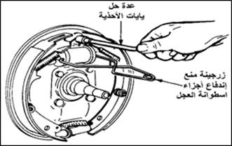
Install a cylinder to keep the parts of the calf cylinder from being pushed out. Keep it attached to the cylinder until the assembly is completed as shown in Figure (12).
· Remove the return springs as shown in Figure (12).
 |
| Figure (12): Removing the strut brake shoes |
· Remove the shoe stabilizer, figure (13) shows the different types of fasteners. In the event that the shoe is attached to a mounting assembly, it can be dismantled when needed.
 |
| Figure (13): The different shapes of the shoe clip on the circuit |
Clean the parts and then check them. Check the springs carefully to make sure they are in good condition. A damaged spring is indicated by a difference in colour, tightened areas (open spring), a change in diameter (the presence of a neck), bending, and an open end as shown in Figure (14).
 |
| Figure (14): The various symptoms that indicate spring damage |
| CAUTION: After disassembling the parts in order, put the parts of each wheel in a separate group. |
Brake shoe assembly:
1. Clean the mounting plate, sand the shoe loader burrs with the mounting plate, and apply a thin layer of high temperature resistant grease to the burrs. Figure (15) shows the locations of the shoe loading burrs.
 |
| Figure (15): Shoe loading burrs |
2. Clean the self-adjusting assembly and rotate the adjusting cam to increase clearance to allow installation of new, thicker bushings. As shown in Figure (16). Then apply a small layer of heat-resistant grease to the self-adjusting screws and the self-adjusting ends that contact the shoes.
 |
| Figure (16): Turning the adjusting cam to allow more clearance for the new thicker bushing |
3. Use grease to lubricate the following areas of the shoe: the area under the shoe stabilizer and the area where it touches the cylinder joint or shoe thrust lever. Use a heat-resistant grease and never use any regular oils or greases.
| CAUTION: * Keep oil and grease off the surface of the liners. * Avoid touching (or catching) the bushings with your fingers as much as possible. (Any amount of grease or oil, even a small amount, on the friction linings may spoil the braking process). |
4. Put the shoes on, and make sure when installing the primary and secondary shoes that each of them is riding in its place. In servo shoes the primary shoe will be the shortest bushings and facing the front of the vehicle when installed.
5. Install shoe anchors and rewind springs and make sure that the springs are installed in the correct place and clipped to the correct hole and use the appropriate tools to avoid damage to the spring as shown in Figure (17).
 |
| Figure (17): Installation of the rewind spring using the special tool |
6. Install the mounting brake assembly (arms and wires) and self-adjusting if it is fitted with the brakes. Move the brake assembly back and forth to ensure freedom of movement, and make sure the shoe assembly is in the correct position.
Adjusting the shoes :
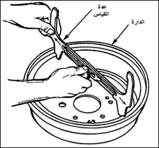
1. Release the retaining brake and loosen the clamping brake cable until you are sure that the shoes are firmly attached to the pivot block. Using the tool for measuring the circuit Figure (18) adjust the measuring tool to the size of the circuit and then fix it in this position.
 |
| Figure (18): Adjust the measuring tool to the diameter of the circuit, then fix it in this position |
2. Fit the other side of the measuring gear onto the shoes. Slide the shoes out by removing the self-adjusting assembly lever/latch and moving the sprocket (star) as shown in Figure (19).
 |
| Figure 19: Remove the lever/ratchet while turning the sprocket |
Keep turning the sprocket until the shoes start touching the other side of the measuring tool, as shown in Figures (20-21).
 |
| Figure (20): Adjust the shoes to size |
 |
| Figure (21): Adjust the measurement to the diameter of the circuit, then adjust the diameter of the shoes |
3. Install the circuit and then install the wheel (tyre).
4. Move the car back and brake the car several times while it is in reverse to operate the brake self-adjustment. Repeat the process several times until you feel the performance of the brake pedal improves. For vehicles whose self-adjustment is actuated by applying the retaining brake, apply the clamping brake several times to automatically adjust the clearance.
There are no reviews yet. Be the first one to write one.

