Checking the condition and level of brake fluid in the master cylinder
Checking Master Cylinder Fluid Level and Condition
The brake fluid level and condition must be checked at least twice a year following the vehicle’s preventative maintenance plan. The driver can, when performing any engine maintenance, by looking at the brake fluid level inside the reservoir in the event that the brake fluid reservoir is made of transparent plastic.
The level of brake fluid in the reservoir decreases as a result of either the wear of the friction linings of the disc brakes, or the presence of an external leak indicated by a significant drop in the fluid level, or the reservoir is empty, Figure (1).
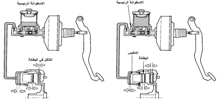 |
| Figure 1: Brake fluid decreases due to wear of the friction linings of the reservoir |
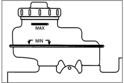
When checking the brake fluid level, make sure that the reservoir is filled to the correct level. There are often two markings on the reservoir to indicate the brake fluid level. The upper mark indicates the maximum permissible “MAX”, which the fluid level should not be increased, and the lower mark indicates the permissible “MIN” and the fluid level must not be less than it. In the case of a transparent tank, the marks are outside as shown in Figure (2) or inside in case the tank is opaque.
 |
| Figure 2: Brake fluid level markers |
If the brake fluid level is low, add more fluid until the fluid level reaches the maximum mark.
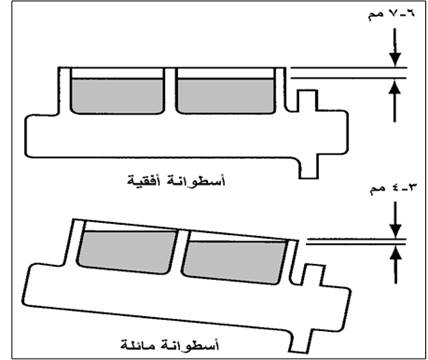
In the event that the tank and cylinder are one piece made of metal, there will be no level indications. In this case, the tank is filled until the liquid level is 6 mm below the edge of the tank. liquid from the edge of the tank as shown in Figure (3).
 |
| Figure 3: Maximum brake fluid level |
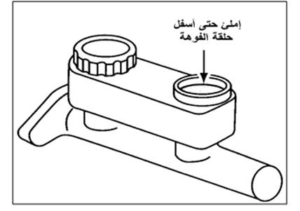
In the case of a dark tank, open the cap and fill the liquid to the bottom of the cap mounting neck (Fig. 4).
 |
| Figure (4): Checking the brake fluid level |
* The oil level is lower than the permissible limit indicated by the illumination of the brake warning lamp on the control panel (dashboard) or by checking the fluid level in the master cylinder reservoir.
Precautions when filling the reservoir
o Do not leave the brake fluid level in the reservoir below the minimum level (too low may cause air to enter the system).
o Do not fill the brake fluid more than the maximum limit (too much fluid will not allow the fluid to expand when it is hot and this will cause the wheel cylinders to increase pressure, which may cause the brakes to load). With the possibility of oil exiting through the tank cap.
o Use the type of brake fluid stated in the specifications each time you add brake fluid.
o In the event that the brake fluid level drops to before the minimum allowed, the condition of the brake system must be checked (brake fluid leaking from the system – erosion of the friction linings). In this case, the cause of the brake fluid drop must be fixed before adding brake fluid.
o If you use Dot-5 brake fluid, do not add any Dot-3 or Dot-4 brake fluid to it, as they interact poorly with each other, and may damage the parts of the system.
o Add brake fluid from a new, unused canister of brake fluid. It is advisable not to keep the brake case after opening it. Even if closed well after use, the liquid is able to absorb water from the atmosphere. This lowers its boiling point (which is why most brake fluid cans are small).
Precautions to be taken when handling brake fluid
§ Always keep brake fluid in the original can, and make sure the cap is tightly closed.
§ Brake fluid should be stored in a low temperature, dry and clean place.
§ Do not use brake fluid near high heat or open flames (the fluid is flammable).
§ Hands must be washed thoroughly after exposure to brake fluid (brake fluid is toxic).
§ Protective glasses must be worn when handling liquid, as the liquid causes damage to the eyes and skin. In case the eyes or the skin are exposed to the liquid, wash the area well with water.
§ Beware of contamination of the friction linings with brake fluid. As the liquid interacts with it and leads to its damage when exposed to heat and pressure. Hand linings and shoes with your hands clean. If the linings and shoes become contaminated with liquid, replace them with new ones.
§ Do not clean brake parts with any metal-based solvent such as kerosene, gasoline, acetone, or paint thinner. Such fluids damage the rubber parts and interlocks, and lead to system damage.
§ Beware of contaminating brake fluid with any type of engine oil or otherwise, as the presence of oil in the system leads to damage to the rubber parts. If this occurs, the parts that have been exposed to the engine oil must be washed, then all the rubber parts should be replaced.
§ Used brake fluid must be collected in a sealed container marked for disposal in a manner that does not harm the environment, and must not be disposed of in public sewage or poured on the ground.
§ Do not spray brake cleaner near brake fluid.
Check the condition of the brake
fluid Check the fluid to make sure that there are no traces of contamination in it, a good fluid is transparent and clean, and in the presence of any of the following phenomena, this requires changing the brake fluid or changing it.
q opaque liquid (darkness indicates the presence of water in the liquid or dust).
q Dark brown color (indicating traces of rust in the liquid).
q The presence of a separation between two layers (indicating the presence of two different types of brake fluid or the presence of mineral oil).
Brake fluid change/replacement
- The brake fluid should be replaced if the inspection indicates that the brake fluid needs to be replaced.
- Brake fluid must be replaced for duration and/or mileage as recommended by the manufacturer. Which may be within 2 years or 40,000 km, whichever comes first.
- The brake fluid must be changed, if brake parts are replaced, or the brake system is severely maintained.
* Changing brake fluid regularly may be more expensive than replacing parts that are damaged as a result of not changing the fluid. But in the case of the ABS system, the parts for controlling the brake pressure are expensive. Therefore, changing the oil on a regular basis is justified economically as well as in terms of safety for the occupants of the car.
| Warning: If brake fluid is spilled on the car’s paintwork or any plastic parts, clean the area immediately and wash the area with soap and water. Do not reuse brake fluid that was in the brake circuit again, but use fluid from a new can. Wipe the lid and neck of the liquid container before opening it so that the liquid does not fall into contamination. Be sure to close the canister of brake fluid well after using it. Beware of brake fluid coming into contact with the eyes or hands, and in the event of this problem, hands must be washed with water and the eye with water that continues to flow, and then it is necessary to go to the ambulance directly. |
A quick check to test the presence of air in the circuit:
1- When you press the brake pedal, you will find that there is resistance to the pedal at the end of the pedal trip. In the event of pressing several quick successive times on the brake pedal, it is noted that the pedal force increases and the remaining distance of the pedal increases. This means there is air in the circuit. It is noted after a period of time the return of the pedal to its initial state.
2- Note the brake fluid in the reservoir. Open the tank cap and have the technician apply several times to the brake pedal and then hold his foot in the pressure position. Then ask the technician to abruptly lift his foot off the brake pedal (slip the foot off the pedal). In the event that a spray of brake fluid rushes to a height of more than 8 cm, this indicates the presence of air in the brake circuit.
| Warning: When performing Test No. 2, the side of the car must be covered so that the brake fluid spray does not hit the car paint and cause damage to it. |
Air eradication of the hydraulic circuit brake Bleeding Air from Hydraulic Circuits
must not contain hydraulic circuit brake on any amount of air. If air enters the circuit, the pressure generated by the master cylinder will not be transmitted to the wheel cylinders (air is compressible).
Air extraction from the system must be performed if air enters it or after removing and reinstalling the brake system connections.
Equipment Required
· Special kit for loosening the brake tube nut.
New brake fluid.
Brake fluid collector and rubber tube (Li).
Precautions to Take When Removing Air from the Brake Circuit (Normal Method)
Two people perform this operation, the technician’s assistant sits in the driver’s seat to press the pedal, and the technician performs the ablation. There must be an understanding between them when communicating during the process steps.
A – The person in the car repeatedly presses the pedal slowly, the rapid pressure will lead to the division of the air bubble into small bubbles that are difficult to get rid of.
C – Start removing the air from the master cylinder first, then perform the ablation process for the furthest wheel from the master cylinder, and then the next one in the distance.
D- It must be ensured that there is a sufficient amount of brake fluid in the master cylinder reservoir, before starting the air extraction process. Add liquid to the tank as needed, and be careful not to get dirt or water into the liquid.
E – Brake fluid must be handled with care. Avoid spilling liquid on the car paint, in case the liquid falls on the car body, wash the liquid from the surface of the paint immediately.
f- Under no circumstances should the old liquid, extracted with the air removal process, be reused.
Air extraction from the master cylinder (the cylinder in a car) :
Air extraction from the master cylinder is performed in case the master cylinder is loosened or the cylinder reservoir has become empty.
If there is an air bleed pin on the master cylinder, connect the bleed air pin to the air bleed pin outlet. If there is no air bleed pin in the master cylinder, do the following:
A – Use the special tool to remove the brake tubes from the master cylinder (fluid outlet). Use a container to collect brake fluid, or put a piece of cloth under the cylinder to prevent the fluid from falling on the car’s parts or on the ground.
b- Slowly the brake pedal is depressed and kept depressed (Figure 5).
| Figure (5): pressing the pedal |
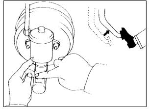
c- Block the exit hole with a finger, then remove the pressure from the pedal in Figure (6).
 |
| Figure (6): Lifting the foot off the pedal |
D- Repeat operations (b) and (c) three or four times.
e- Use the same special tool to connect the tubes to the master cylinder.
Air extraction from the hydraulic circuit (wheel cylinders):
1- Connecting the rubber tube (Li) to the wheel cylinder:
A- Release the clamping brake.
b- Lift the plug of the excision screw off the screw.
c- Connect the rubber tube to the extirpation screw and place the other end of the tube in a container filled halfway with brake fluid (Fig. (7)).
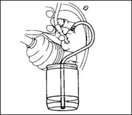 |
| Figure (7): Connecting the lesion to the excision path |
2- The procedure for removing the air from the brake circuit:
A- Slowly press the brake pedal several times (dip operation).
b- Keeping the pedal pressed down, loosen the excision screw until the liquid starts to drain, then re-tighten the excision screw with the required torque.
c- Repeat the previous steps until no air bubbles appear in the bowl.
D- Repeat the previous steps for each calf cylinder as in Figure (8).
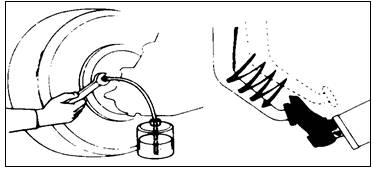 |
| Figure (8): The process of removing air from the brake |
e- Check that there are no leaks
and – Install the eradication pin plug for each wheel.
| CAUTION: * Note the brake fluid level in the master cylinder reservoir, no air extraction and the oil level is low. * Do not use strong pressure on the brake pedal during the eradication so as not to turn the air inside the system into small bubbles that are difficult to get rid of, and for this the eradication process should not be performed while the car engine is running so as not to increase the pressure on the pedal. * It is recommended that the pedal does not reach the floor of the car during the eradication so that the piston does not move forward in an unused area inside the cylinder, which may cause damage to the primary plate. For this, it is recommended to place a wooden block under the pedal, with a thickness of 25 mm, so that the pedal does not reach the floor during excision. |
3- Arranging the ablation procedure
The arrangement of air removal from the wheels is extremely important to ensure that all air is removed from the brake circuit. The order of ablation varies from vehicle to vehicle, so you should refer to the maintenance manual for the vehicle performing the ablation procedure for its brake system. Figure (9) shows the arrangement of the common air ablation procedure in different hydraulic circuits.
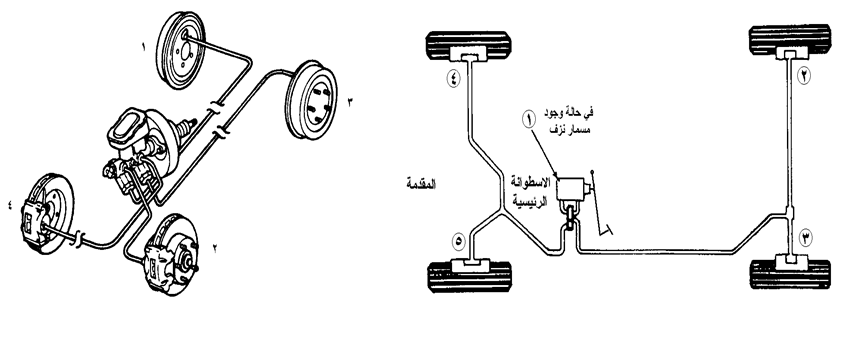 |
| Figure (9): The order of the excision procedure for the bilateral circle A – anterior posterior b – diagonal |
Different methods of removing air from the brake circuit
a. Manual bleeding:
It requires someone to assist the technician to apply pressure on the peds. See Figure (10).
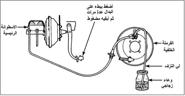 |
| Figure (10): Removing the air from the brakes by the technician |
B. Pressure bleeding:
It is performed using a device that is installed on the opening of the master cylinder tank and uses an air pressure of no more than 140 kPa (low pressure), see Figure (11).
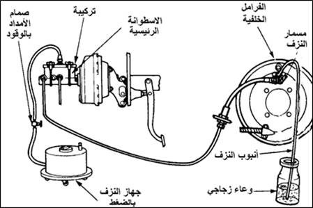 |
| Figure (11): Extraction of air from the brakes by means of a pressure device |
T. Vacuum bleeding:
It is done by using a vacuum pump (manual or electric) to withdraw fluid from the ablation valve into the device container, see Figure (12).
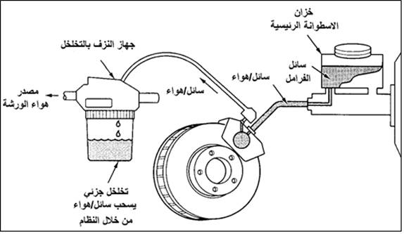 |
| Figure (12): Extraction of air from the brakes using a vacuum device |
d. Gravity bleeding:
It is done by opening the eradication valve and without pressing the pedal. And wait for a period (several minutes) until the liquid comes out of the system without air, see Figure (13).
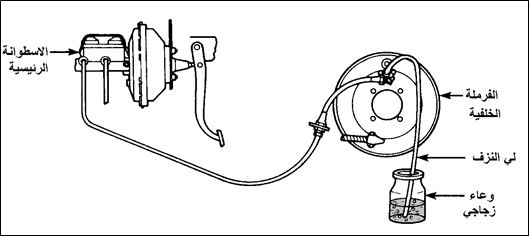 |
| Figure (13): Extraction of air by gravity |
* Method B, C and D does not require the presence of an assistant to assist the technician in conducting the experiment.
* Method A, B requires the use of a special combination to make the calibration valve in the brake circuit open during the ablation procedure, Figure (14).
 |
| Figure (14): If the calibration valve is found in the circuit, it must be made open for the possibility of performing the eradication process, and this is done through a special (kit) combination |
Check
master cylinder condition: When diagnosing brake circuit malfunctions, always start at the master cylinder, lift the brake fluid reservoir cap and look at the surface of the brake fluid while the technician assistant applies pressure to the brake pedal.
You should notice a movement or rush of fluid from the compensating hole for both the primary and secondary circuits of the cylinder. This indicates that the primary interlock does not impede the movement of the fluid and that the compensation hole is open, and that the movement of the pedal pushes the fluid into the tank at the beginning of the pressure on the pedal.
In the absence of movement of the fluid, this is due to:
– The height of the brake pedal is not adjusted (the height of the pedal or the length of the thrust shaft can be adjusted), and this makes the primary interlock pushed forward too much and closes the compensation hole
– the primary interlock has swelling, and makes the interlock itself The compensation hole is closed.
Master Cylinder Replacement
In the next section, we will show the steps for changing the master cylinder that works with a vacuum servo in a brake system that does not have an ABS system.
* Before attempting to change any part of a brake system that has an anti-locking wheel system, review the maintenance manual.
Steps to Change the Master Cylinder
1. Stop the vehicle and place an obstruction behind the tires.
2. Loosen the wires of the brake fluid level indicator sensor (if any).
3. Before loosening the servo drum nuts, place a clean cloth under the master cylinder to catch any brake fluid spills.
4. Loosen the cylinder mounting nuts with an appropriate wrench.
5. Loosen the metal tubes connected to the side of the cylinder (number 2 or 4) as shown in Figure (15). Use the appropriate tool and pull the brake tubes away from the cylinder body.
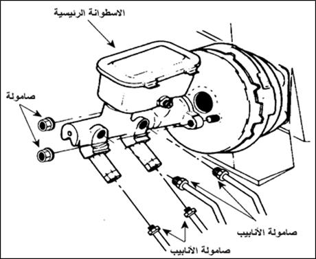 |
| Figure (15): Removing the master cylinder |
6. Pull the cylinder from the vacuum servo.
7. Rotate the cylinder so that the piping holes are up to prevent brake fluid from spilling when the cylinder is raised.
8. With the drum outside, lift the reservoir cap and drain the brake fluid into the appropriate container.
9. If necessary, remove the tank from the old cylinder and install it in the new cylinder, lubricate the sealing ring before installing the tank as shown in Figure (16).
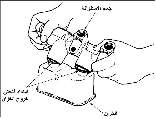 |
| Figure (16): Installing the tank with the cylinder |
10. Put brake fluid into the reservoir and remove the air from the cylinder as described in the next paragraph.
11. After the removal process is completed, install the cylinder in the car, place the cylinder in place on the servo surface and tighten the mounting nuts according to the torque specified in the specifications.
12. Place the brake tubes near the exit holes of the cylinder, loosen the removal tubes and quickly install the brake tubes in the proper order, then tighten the tube nuts by hand to prevent any leakage.
13. To ensure that no air enters the cylinder during the process of removing the removal tubes and installing the brake tubes, air is removed from the cylinder while the cylinder is installed in the car as shown in the following paragraph.
Air extraction from the master
cylinder A – cylinder outside the vehicle:
Air is removed from it on the work platform when replacing the master cylinder or when maintenance and repair is done outside the car, and the process is called bench bleeding.
1. Attach the roller to the vise with the front part slightly raised.
2. Fit the tubes of the ablation kit to the fluid outlet holes of the cylinder.
3. Lift the reservoir cap, then fill each compartment of the reservoir halfway with brake fluid.
4. Insert the ends of the excision tubes into the tank, one in each chamber, bring the end of the tubes near the bottom of the tank and hold them in this position.
5. Use a screwdriver or a shaft to slowly affect the primary piston, as shown in Figure (17).
6. Push the plunger all the way to the end.
7. Reduce the force and allow the piston to return to its original position.
8. Repeat steps (5-7) until no air bubbles are seen coming out of the excision tubes.
9. The end of the excision tubing is closed to the reservoir (by means of a paper clip or the like) before lifting the cylinder from the vise.
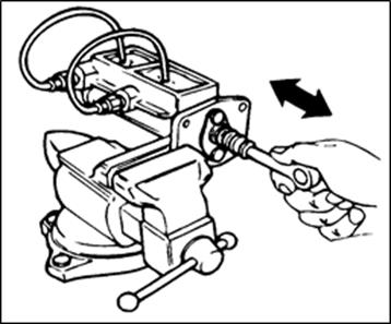 |
| Figure (17): The process of removing air from the master cylinder on the platform |
B – The cylinder is installed in the car:
this process is carried out by the technician and his assistant.
1. Make sure you put enough cloth under the drum to prevent brake fluid from spilling onto the floor.
2. The brake fluid reservoir must be filled with brake fluid to MAX.
3. Have the assistant technician slowly depress the brake pedal and maintain pressure, loosen the tightening of the primary circuit nut and note the air escape and tighten the nut. The same procedures were performed for the secondary department. Make sure to tighten the nuts before removing the foot from the brake pedal.
4. Repeat the previous step until no air bubbles are seen with the brake fluid escaping.
5. Tighten the brake tube nuts and fill the fluid reservoir to the specified level.
6. Before starting the car, make sure that the brakes work as follows:
A – For cars with automatic gearbox, press the brake pedal and start the car, then with the gearshift position changed to forward gear and make sure that the brakes are able to stop the car.
b- For cars with a normal gearbox, start the engine and then put the transmission in the first gear position and by relieving the pressure on the clutch pedal while pressing the brake pedal and make sure that the brakes are able to stop the car.
Master-Cylinder Overhaul Repair (Packaging) Master-Cylinder Overhaul
Objective:
Removing the master cylinder from the car, dismantling the master cylinder, checking the cylinder and its parts, changing damaged parts, assembling the cylinder, installing the cylinder in the car, removing air from the cylinder.
Required equipment: A
special gauge to measure the servo thrust arm clearance.
A special key to loosen the brake tubes.
Brake fluid.
Brake fluid dispenser, rubber tube.
Special grease (Lithium soap base glycol grease).
Master cylinder repair kit.
Work steps:
1- Remove the brake tubes from the master cylinder:
Use the special wrench to loosen the brake tubes attached to the master cylinder. As in Figure (18) and Figure (19), as well as loosen the connection of the brake fluid level sensor (Figure (20).
 |
| Figure (18): Removing the brake tubes connected to the drum |
| Warning: • Do not attempt to loosen the tubes connected to the master cylinder with a regular wrench, as this will damage the nut. • Beware of spilling brake fluid on the car’s paintwork. If this happens, wash that area immediately. |
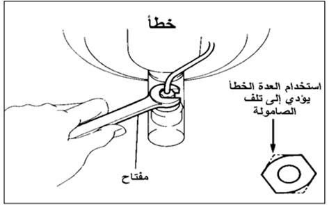 |
| Figure 19: Using the correct equipment |
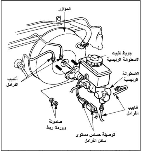 |
| Figure (20): Removing the brake tubes and the brake fluid level sensor connection |
2- Emptying the brake fluid from the reservoir on the workbench. Lift the brake fluid reservoir cap and dispose of the fluid in a container (Figure 21).
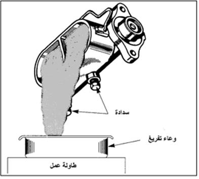 |
| Figure (21): Brake fluid drain |
3- Loosen the piston positioning
screw : Using a screwdriver, push the pistons in to the end and then loosen the piston positioning screw and interlock.
Note: Wrap the screwdriver tip with a cloth before pushing in on the screwdriver so as not to scratch the surface.
4- Loosen the piston fixing ring on the cylinder:
Loosen the mounting ring installed at the end of the cylinder using pliers to remove the fixing rings. Depress the piston when removing the o-ring, and after removing the o-ring, gradually reduce the pressure and allow the spring to push the piston out. Remove the pistons, springs and interlocks from the cylinder.
If the cylinder has a fit valve or a pressure-retaining valve attached to the cylinder, loosen them. Also loosen any electrical connections or switches attached to the cylinder.
| Warning: The piston positioning bolt must be loosened before lifting the piston retaining ring. If the bolt is lifted after removing the washer ring, it may cause the pistons to be pushed out with great force, which may result in injury to the person working or those around him. |
5- Inspect the master cylinder and its parts:
Note: Before performing the inspection, clean the cylinder parts with compressed air.
A- Check the cylinder bore for any scratches or rust, and if there are any, clean or change the cylinder.
b- Check the piston and plates for any wear, scratches, cracks, or bulges. If any part needs to be replaced, use new parts from the cylinder repair kit.
C – Measure the cylinder and piston hollows to ensure that there is no wear (Fig. 22). If corrosion is present, make the required change.
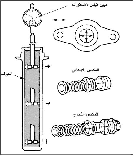 |
| Figure 22: Cylinder and piston gauge points |
6- Assembly of the master cylinder:
apply the special grease to the rubber parts indicated by the arrows in Figure (23).
 |
| Figure (23): Cylinder pistons and interlocks |
Insert the pistons into the cylinder (Fig. 24). In cylinders with a pressure-retaining valve, install the valve first. In the event that the front piston is positioned by means of a bolt, insert the front piston and press it against the spring, then install the bolt, then insert the rear piston assembly and then install the retaining ring. Be careful when inserting the pistons so as not to damage the interlock as it passes over the exit holes.
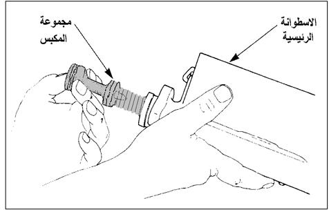 |
| Figure (24): Installing the piston group on the cylinder |
7- Installing the tank:
Install the tank with the use of a circular knitting ring when needed. Then make any electrical connections the cylinder head may need.
8- Performing the removal process outside the car:
Refill the reservoir with brake fluid and then perform the process of removing the air for the cylinder on the table before installing it in the car (Fig. 25).
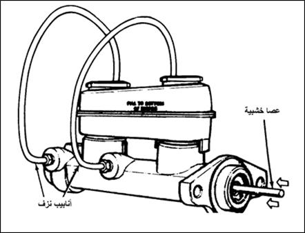 |
| Figure (25): Air excision on the table |
9- Checking the length of the servo thrust arm:
Use the methods used to measure the length of the servo thrust arm, and adjust the length according to the specifications when needed.
10- Installing the cylinder in the car:
A- Install the cylinder on the fixed screws in the servo.
b- Install the connecting nuts with the bolts, then tighten them with the torque stipulated in the specifications.
C – Lift the plug from the exit holes and install the brake tubes and tighten them well.
D- Install the electrical connections to the brake fluid level indicator sensor, if any.
E- Connect the ground connection to the battery.
And – when air is removed from the system. Start with the master cylinder, then the wheel cylinders.
Master cylinder drip test:
Excessive wear on the friction linings is often due to the brake pedal not fully returning to the no-brake (brake-loaded) position. This is due to the couplings of the wheel brake pistons or the brake actuator rear warning lamp switch.
If the brake pedal is not fully reversed, this means that the primary interlock will be in a position to shut off the master cylinder compensation hole. To confirm the cause of the problem
– remove the two brake lines from the master cylinder. In this case, the brake fluid should drip at a rate of 1 point per second, which is why this test is called the “master cylinder drip test.” If there is no dripping, this means that the brake pedal is preventing the master cylinder from being released from the non-brake position.
Have the assistant technician pull the brake pedal to release the brakes. If the cylinder starts to drip, this means that the problem is that the rear brake actuation warning switch, the cruise control switch, or the pedal travel stabilizer are not set. If the master cylinder remains in a non-drip state.
Partially loosen the master cylinder bolts with the servo. If the master cylinder starts to drip, this indicates the servo thrust lever is too long and needs to be adjusted. If the master cylinder remains in a non-drip state. The problem is with the master cylinder itself.
Check the brake fluid for contamination. If any engine lubricating oil, power steering oil or automatic transmission oil is used, it will cause deformation and stretching of the primary cylinder interlock, and the compensation hole will be closed. If brake fluid becomes contaminated, the cylinder must be rinsed and any rubber part used in it should be replaced.
Check and replace the disc calf brake Alanfrajah
Checking and Replacing of Wheel Cylinder
extraction cylinder calf of the car:
1. Lift the car crane.
2. Unscrew the frame.
3. Remove the circuit.
4. Remove the brake shoes (see the process of removing the shoes)
5. Remove the brake tube from the cylinder, do not bend and remove the tube from its place, as this may damage the tube or make it difficult to return it to its place when installing.
6. Loosen the rear screws to secure the cylinder to the brake parts mounting plate as shown in Figure (26).
7. Remove the roller from its place.
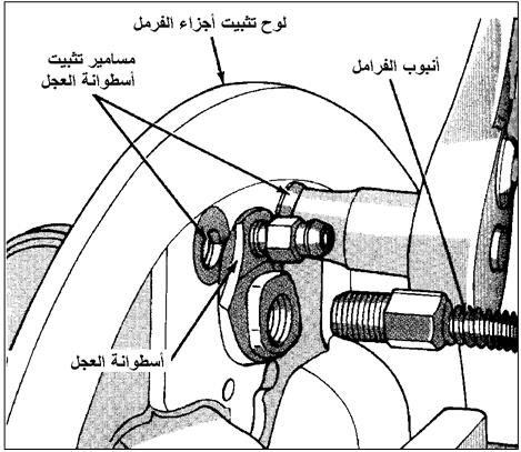 |
| Figure (26): Removing the wheel cylinder from the mounting plate |
Removing and checking the wheel cylinder:
1. Remove the dust guard from the wheel cylinder.
2. Pull the inner parts of the cylinder (pistons, coils, and springs) outward. Figure (27) shows the parts of the calf cylinder.
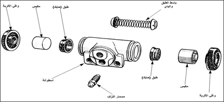 |
| Figure (27): Wheel cylinder parts |
3. Clean the drum parts with the recommended solution. Some pistons are made of iron and have a lubricant on them. These pistons are not washed, but only wiped.
4. Clean the inside of the drum with a special cloth or a softener can be used to remove pits or scratches, then wipe the inside of the drum with a cloth dampened with brake fluid.
5. Rinse the drum at least twice and then use compressed air to dry the drum. Never allow the roller to dry out by letting it air.
6. Check the cylinder If there are any scratches or pits in the cylinder, especially the part that the piston and interlock move through, the cylinder must be replaced.
7. Check the clearance between the cylinder wall and the piston. This should not be more than
0.005 inches (0,127 mm) for cylinders with a diameter of 1 inch (25.4 mm).
or less (0.007 in (0.178 mm) for cylinders with a diameter larger than 1 in.
Use a feeler gauge when measuring.
8. Check the condition of the piston, if there are any signs of rust or scratches, it must be replaced if it is not Well, figure (28) shows the steps for dissolving and disassembling the cylinder parts and checking them.
 |
| Figure (28): Steps for disassembling and checking the calf cylinder: Remove the wheel roller from the mounting plate.B – dismantling and washing the parts of the cylinder. C – Inspect the cylinder and parts. d- Check the cylinder diameter with a non-pass gauge. e- Measurement of the clearance between the cylinder wall and the piston. |
Assembling and installing the wheel cylinder :
1. Lubricate the inner surface of the cylinder, piston and new interlock with brake fluid, then assemble the cylinder.
2. Install the dust guard in place to keep the pistons in place inside the cylinder.
3. Attach the cylinder to the mounting plate and then connect the brake tube.
4. Put the shoes on and the circuit.
5. Perform a pneumatic extirpation (see Hydraulic circuit pneumatic extirpation).
6. Install the wheel.
| CAUTION: * Make sure when installing the knitting plate that the edge of the plate is facing inward. * When there is a tray opener (extended) in the cylinder, it must be installed by placing it inside the cylinder. * Carefully insert the plate into the cylinder so as not to damage it during entry. * Do not push the plate in to the edge of the filler hole, as this will not block it and prevent the entry of brake fluid. |
Examination of pipes and Yat brake Checking Brake Line Pipes and Hoses
are used and Yat – filled brake fluid to move the brake hydraulic pressure generated in the master cylinder to cylinder calf tubes. In the event of an external leak from pipes or fibers, the pressure will not reach the cylinder cylinders, Figure (29).
Inspect the condition of the brake
cylinders and tubes : The condition of the brake cylinders and tubes is checked periodically and replaced immediately in the event of slight traces of damage (Fig. 30).
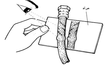 |
| Figure (30): Inspection of brake cylinders and tubes |
| Attention* The examination should be performed under adequate illumination. * Track vehicle inspections along the perimeter and around the perimeter. * Use a mirror if necessary. * Turn the wheels of the vehicle far to the right or left when performing the inspection. |
1- Check for external brake fluid leaks:
(a) Check the brake tube connections for traces of oil leaks.
(B) Check the disc brake cylinder and the strut brake mounting plate for traces of leakage (Fig. 31).
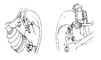 |
| Figure (31): Examination of leak sites |
* It also indicates the presence of an external leak of the fluid by decreasing the oil level in the master cylinder tank at a rapid rate with frequent refilling.
2- Inspect the brake tubes:
(a) Check the brake tubes for any damage or rust.
(B) Make sure that the tubes are installed in the correct place, Figure (32).
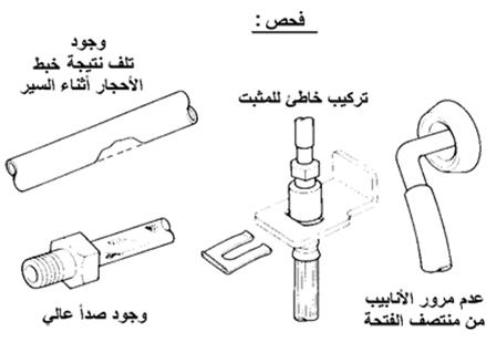 |
| Figure (32): Checking the brake fluid tubes |
3- Check the brake
mechanics : Check the brake mechanics for cracks, damage, deflection or swelling (Fig. 33).
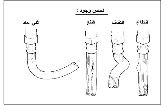 |
| Figure (33): Checking the condition of the brake cylinders |
Replacing Brake Line Pipes and Hoses
1- Replacing the metal brake tubes: Remove the
tubes from the car
1- When changing one of the tubes, clean the connections at the end of the tube.
2- Leave the tube stabilizer attached to the chassis until you have finished dismantling the connections with the ends, as this will facilitate dismantling.
3- Use a pipe wrench to loosen the pipe connections, in the case of a pipe connected to me, use two wrenches to loosen them (Figure 34). If a replacement pipe is not installed immediately, block the connections hole in the car so that dust and the like do not enter the circuit.
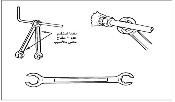 |
| Figure (34): Method of dissolving tubes |
4- Loosen the linkage stabilizer on the chassis and lift the link. Inspect the fastener and its screw for possible reuse, in case of any damage, replace them. If a tube protector is present it can be kept for reuse with the new tube. In the case of making a tube in the workshop, I keep the old part to make a new tube of the same length and shape.
Installing the pipes in the car
1. To install the pipe, put it in place on the chassis, then install the pipe stabilizer and not be tightened so as to facilitate the installation of connections to the ends.
2. Use the appropriate pipe wrench to install the connections, then tighten (earring) on them and then tighten the fixing screw.
| CAUTION: * When replacing tubes, adhere to the use of tubes of the same diameter as the original tubes. The brake response time is determined by the diameter of the tubes. |
2- Replacing the brake fittings.
Removing the brake
fittings from the car a- Clean around the couplings before starting to disassemble so that dirt does not enter the system.
b- Use a pipe wrench and start loosening the pipe nut from the (female) connection or loosening a connection (free-rotating nut) with the torsion end. When disassembling a connection at the end of mine, it is preferable to use two pipe wrenches, one for each connection (Fig. 35).
 |
| Figure (35) Dismantling the brake mechanisms |
—————————–
- Unscrew the pipe fastener with friendly buttons.
- Disconnect the tube from any fasteners.
– Use a tubing wrench to loosen the second coupling of the saddle or wheel cylinder (Figure 36).
– In the event that another device is not installed immediately, block the coupling hole in the car to prevent dust and the like from entering the system.
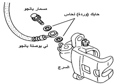 |
| Figure (36): Removing the toe from the saddle (banjo connection) |
| Caution: * When replacing fittings with a free-rotating nut with one end of it, it must be loosened first. * When replacing cylinders with a (memory) connection on one end and a (female) connection on the other end connected to a nut (widening outward) to the brake tube, start with the feminine connection. * In the event that the one connected to the (banjo) connector on one end to connect with the saddle, start by removing this end first and then unscrewing the connection on the other end. * Sometimes the saddle joints are left threaded. Threads distinguish left-hand bolts by having holes in the fair surface of the nuts and bolts. |
Installing cylinders in the car
1. In the event that the one that has a masculine tip, connect it to the saddle first, install your interlacing (copper rose) if needed (Fig. 37).
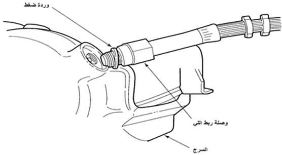 |
| Figure (37): Connecting the strap to the saddle |
2. If there is a banjo connector on the end of the harness to connect to the harness, plug it in first. Install the banjo bolt and install a copper rosette on both sides of the joint surface. Do not tighten the banjo bolt until you have attached the connection to the other end.
3. Pass the torsion over the fixing areas and install the torsion fixtures.
4. Insert the free end of the torsion through the stand lever.
5. According to the twist design, connect the brake tube nut (widening outward) to the end of the torsion (female) coupling. Or connect the free nut to the brake tube (Fig. 38).
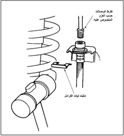 |
| Figure (38): Installing the toy to the chassis |
6. Use a piping wrench to tighten the connections and hold the wrench to another piping wrench to prevent it from twisting during installation.
7. Install the stabilizer to fix the position of its holder.
8. If the banjo bolt is left loose in step “2”, adjust the banjo joint to get the best fit position and then tighten the track.
| Attention: * When replacing the cylinders, the same length of the original cylinders must be used. As the longer length may lead to friction with the chassis, and the shorter length may lead to damage when the moving parts of the wheel reach the end of their movement. * After completing the installation of pipes and fittings, check for any external leakage of brake fluid. If there is a leak, tighten the connections. * Upon completion of the installation of the mechanisms, make sure that they do not come into contact with the wheels when changing the direction of the wheels during the steering movement, or during the movement of the car body up and down in relation to the suspension system. |
There are no reviews yet. Be the first one to write one.

