In the automobile design , the shape/style of the automobile layout describes the location of the engine position and the position of the driving wheels . There are many different combinations of engine position and steering wheels for cars in use. The factors that affect the choice of car design depend on the applications , cost , complexity , reliability , available space , weight distribution , and car handling characteristics .
The shape/style of the vehicle can be divided into several categories:
Front engine rear and push front-engine, rear-wheel- drive (FR) is a pattern in which the engine forefoot Front the engine , and calf commander / defended at the rear a rear-wheel drive – the drive . This traditional style of cars through most of the twentieth century. Modern vehicle design uses a front-engine, front-engine, front-wheel drive (FF) .
The first car with engine style in front of me and drag the rear (FR) was Bmodel Banhard Panhard 1895 , so called this pattern Banhard system “Système Panhard” in the early years. The style is characterized by the reduction of mechanical complications, as it allows the transmission to be placed in line with the engine, good weight distribution of the car. In contrast, the FF car eliminates the need for a drive shaft (replaced with the transaxle (lower combined weight)), but has the disadvantage of concentrating all the weight in one place.
For the proportional reduction of the shaft, the transmission is usually divided into two parts: the gearbox and the final drive . The gearbox is usually manufactured and has a higher gear ratio of 1:1, which provides some mechanical advantages. The final drive , on the rear axle, reduces the speed to a suitable speed for the wheel, and doubles the torque. Where power is the product of torque x angular velocity.
Divide the reduction ratio in two stages (i t = i g xi f ) , where i t the total reduction ratio, i g the gearbox reduction ratio (variable by shift), i f the final differential reduction ratio (constant ratio); It rotates the shaft faster for any given power, reduces torque, and allows for a shaft with fewer dimensions and lighter weight.
In an era when gasoline prices were low and cars were heavy, the mechanical advantages of front-wheel drive and rear-wheel drive outweighed the weight disadvantages. And this style remained prevalent over all other styles until the seventies. After the 1973 oil embargo and the 1979 fuel crisis, American cars were gradually switched to front-engine and front-wheel drive.


The drive shaft is called by many names, the transmission shaft, the shaft, or the cardan shaft, the drive shaft (drive shaft, driveshaft, driving shaft, propeller shaft (prop shaft), or Cardan shaft) is a mechanical unit of power transmission (torque). torque and rotation ), which is usually used to connect other components of the drive train that cannot be connected directly due to distance or the need to provide relative motion between them.
 |  |
 |
The propeller shaft connects the gearbox to the final drive gears of the car through the universal joint and acts as the drive shaft . The shaft transmits power from the gearbox to the rear axle. Usually the column is made of a tubular section, the column is made of a sheet of iron that is rolled into a hollow column with a cylindrical section, and it is made of one or two parts. The two-part design has a rubber loading seat in the middle.
It works in cars with front -engine and rear-wheel drive front -engine, rear-wheel-drive layout to connect the gearbox connected to the engine, and the differential gearbox connected to the axles of the driving wheel.
Required functions of the driveshaft:
* torque transmission, “torque fatigue”,
* transmission of rotational motion, the rear end of the shaft is connected to the driving wheel axle “the wheel axle is connected to the car chassis with a flexible connection by means of the suspension system spring”.
The torque transmission and transmission are through two different vertical planes, the shaft connecting the gearbox and the crankshaft case (there is a difference in height between the front of the shaft connected to the gearbox output shaft, and the rear of the shaft connected to the chassis of the differential gearbox).
The loads to which the drive shaft
is exposed : The shaft is subjected to many loads during its work:
* Torque, output torque of the gearbox (its value changes according to the gearbox shifts, the maximum value of the transmitted torque = the maximum value of the engine torque x the reduction ratio for the first gear “the highest reduction ratio” gearbox”).
The shaft can be manufactured hollow as the middle part near the center contributes to bearing a small part of the torsion stress caused by the transmission of torque.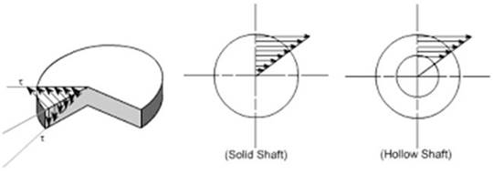
* Rotational speed, gearbox output speed (its value varies according to the gearbox shifts, the maximum value of the transmitted speed = the maximum speed of the engine “direct gear”, or the maximum speed of the engine ÷ the ratio of overdrive “less than 1.0 ” )
* bending, as a result The weight of the shaft, and the centrifugal force if the center of gravity is not located on the shaft axis.
 |  |
| Solid shaft, with a large bend due to the heavy weight, leading to high vibrations. | To overcome bending, the shaft is made hollow, with a larger diameter to withstand bending stress, and lighter in weight. |
The driveshaft is part of the transmission system in front-engine and rear-wheel drive vehicles, and connects the front-engine-mounted gearbox to the rear-wheel drive crankshaft case. Its function is to transmit power (torque, rotational speed). The shaft is subjected to:
– Torque, and therefore it is made of a suitable diameter to transmit torque.
Bend due to weight, so it is made hollow to light weight.
– Vibration as a result of unbalance and moderation under the influence of rotational speed, and therefore balance is made for the shaft
– for the vertical movement of the wheels, it is overcome by the universal joints, and the sliding joint with swivels
– As for the drive forces for the wheels, they are not transmitted via the shaft, but are transmitted to the car through the leaf spring connections and assemblies connected to the car chassis for cars with rear drive axle, or the outer tube of the torque tube, or independent suspension parts and accessories for the cylinder spring. 
Vector torque, shaft exposed me torsion and shear stress shear stress is equal to the difference between the determination of entry and pregnancy. Therefore, it must be strong enough to withstand stress, and avoid too much weight as this will increase its inertia .


Column parts and components:
Shaft / rotation is made mainly of three main parts (column, public links, link slider) .:
Column Shaft : is the hollow tube of steel, its diameter and length commensurate with the car and torque. Cars with long chassis need more than one, two, or three poles. The columns are hollow to reduce weight, but with a large diameter to withstand stresses. It uses high-quality steel, and sometimes aluminum. It must be prepared and balanced to avoid vibration.
Administration column consists of a single column single or consists of several shafts connected respectively (2 or 3) to reach the transmission / gearbox from the front mailbox gears the difference the back.
Single column a Single Propeller Shaft :
shaft consists of a cylindrical shaft hollow, public links parties, link sliding.
 |  |
 |
The double propeller shaft
is added to the single shaft, the center support holder, in addition to a third universal connection.


General links the Universal Joint :
shaft transmits the engine torque to the rear axle through one or more public links. Which consists of: (1) Spider Spider (Saliba the cross ) that allows the column to rotate with an angle between him and income axes or output, (5) Filangh / lip Flang : relate Filangh shaft rotation gear box, Filangh on the other hand , connected to mailbox attached column .
The universal joint called by many names (universal coupling, U-joint, Cardan joint, Spicer or Hardy Spicer joint, or Hooke ‘s joint) is a joint or coupling in a rigid shaft that allows it to bend in any direction. It is used in columns that transmit rotary motion . A universal joint is not a constant-velocity joint . Allows shaft to flex when shaft angle changes. It absorbs bumps and bumps in the road.
Link Sliding Slip joint :
link sliding Slip joint The shaft uses splines to transmit torque and to allow a change in length due to wheel movement.
Consisting of (2) tube is courted splines internal called quantum / Cover Sleeve . As well as from external shafts (3) that slide into the outer shafts in the event of a change in the distance between the transmission output shaft and the differential gearbox input shaft. The outer shafts at the end of the shaft mesh well with the inner shafts in the tube and transmit torque and movement. It also allows, by slipping, to change the length between the drive unit and the driven unit without damage to the input bearings of the differential gearbox or the output of the gearbox.

Chairs Moderation download Center Support Bearing :
is often to be in the middle (5), column with many parts (duo, trio), and the support column and Tthbyn axis of rotation management.
In the case of long shafts made of two parts. A center support bearing is used to provide support for the shaft, reduce stress on the transmission parts, and allow the shaft to rotate freely. When two or more drive shafts are joined together, their alignment is maintained by means of a rubber bushed center support bearing . It is bolted to the chassis or under the car body. It supports the center of the shaft where the two parts are connected together. 


Center support bearing.
Inside the chair there is a ball bearing that allows the shaft to rotate freely. The outer circumference of the marble ball bearing is fixed in a doughnut-shaped mount . The rubber mount prevents vibration and noise from entering the vehicle space.
Types of drive shafts :
There are two common types of drive shafts , Hotchkiss drive and Torque Tube Drive for front-engine and rear-wheel drive FR cars .
All shaft-drive systems consist of a driveshaft (also called a propeller shaft or Cardan shaft ) that extends from the transmission/gearbox in the front to the differential crankcase in the rear. The distinguishing feature of the Hotchkiss management is that it uses universal joints Both ends of the column, and is closed to them. In the torque tube drive, one common joint is used at the end of the shaft, and it must be a constant velocity joint . In the Hotchkiss drive system, slip-splines are used to prevent thrust from being transferred to the drive shaft from the axle, allowing the use of parallel leaf springs on the rear axle. In a torque tube system, this thrust is carried by the torque tube to the transmission and from there to the engine and engine bases to the chassis. The exhaust pipe can use limiting elements, such as Panhard rods , allowing the use of a coil/cylinder spring.
In contrast, Hotchkiss management transfers thrust to the car’s chassis using parts of the suspension such as leaf springs or trailing arms.. A ball and socket joint called a torque ball is used at one end of the torque tube to allow relative movement between the shaft and the transmission as a result of suspension movement. In some cars, a flange and pillow fitted in place of the ball and socket were used. Since the torque tube does not restrict the axle from side-to-side movement, a panhard rod is usually used for this purpose. The torque tube assembly and Panhard shaft allow the use of a coil spring in the rear to give a good ride.
In addition to transmitting thrust, the torque tube is hollow and contains a shaft. Inside the torque ball there is a universal shaft joint that allows for relative movement between the shaft ends. In most applications the shaft uses a single universal joint which has the disadvantage of causing velocity fluctuations in the shaft when the shaft is not level. Hotchkiss management uses two universal joints that have the effect of canceling out velocity fluctuations and giving a constant speed even when the shaft is not flat.
The torque tube is usually heavier and tightly ties the rear end together, ensuring good coordination and discipline under all conditions.
Hotchkiss thrust consists of a shaft connecting the transmission and the small gear shaft of the crankcase. A U joint is used on the front and back of the shaft. Hotchkiss drive transmits torque from the transmission/gearbox output shaft to the differential. In some cases, two parts of the shaft are used to reduce vibrations and facilitate installation (in this case, three universal joints are used). The two-part (two-column) type needs bearings sealed sealed as the shaft intermediate bearing center. Rubber is added to it to reduce noise and vibration. Hotchkiss has a spring paper system prevents the arrival of brake torque or acceleration torque to the column, and is not transferred to the chassis of the vehicle, as is the transfer of momentum wheels generated between the tires and the ground to the car chassis through bra spring Bracket .
Hotchkiss drivetrain was the dominant mode of power transmission for front-engine and rear-wheel drive FR cars during the 20th century. The name comes from the French company Hotchkiss , which was the first to use it. During the first part of the twentieth century, transmission was by shaft style shaft drive and chain-drive . In addition to the transmission system “tube Torque Torque Tube “, which was popular until his fifties 1950 , but it is still used in some cars FR The .
Hotchkiss management system : the Drive Hotchkiss
* Hotchkiss management system Hotchkiss is the simplest and most prevalent in the suspension of suspension of the rear axle a rear Axle .
Hotchkiss management system includes springs and rear axle position or position. It uses a rigid axle with two pairs of leaf springs attached to the axle as far from each other as possible.
* Hotchkiss drive consists of a leaf spring, a shaft with two universal joints and a sliding coupling.
* The front end of the leaf spring is installed in an axle mounted on a chassis-mounted bracket. Where the rear end of the spring is fixed in a swinging bearing by means of a sliding bushing.
* The leaf spring is center-fitted with the rear axle blank/casing.
* The spring carries the weight of the car, and bears the reaction of the thrust force.
* The thrust and brake torque are absorbed by the front part of the leaf spring as indicated by the dotted lines in the figure.
* During driving and braking, the position of the small gear of the differential gearbox changes, which changes the shaft length and angle, which are adjusted by the universal joint and the shaft sliding coupling.
* In the case of a working connection at the front end only, this will lead to bending or damage to the drive shaft. To avoid this, another universal joint is installed at the rear end.
* In case the vehicle has a bump, the rear axle rises up and down and the axle moves in a circle with the front spring stabilizer on the chassis as the center. Meanwhile, the length of the drive shaft will change, which will be adjusted by means of a sliding joint .
Pushing torque tube Torque Family Tube the Drive :
push a tube in which torque is transferred to the wheels push the car through the tube, which is a solid hollow column tube extends from the transmission to the rear axle tray. One end of the shaft is fixed to the differential gearbox to the axle by means of bolts. The other end of the transmission is connected by a Torque Ball . Shaft torque tube installed inside, a common unit U-joint ride in the ball Torque Torque Ball , the end of the column empty in axle housing end and connected via Courted splined with the small gear shaft Pinion Gear Shaft . The thrust from the wheels is transmitted through the torque tube to the torque ball, to the transmission , to the engine , and eventually to the frame through the engine mount . Thus, the car is pushed forward.
The torque referred to in the name is not the drive shaft torque, along the axle of the vehicle, but the torque generated by the wheels. The design problem that the torque tube solves is how to transfer the traction forces generated by the wheels to the car’s chassis. The “torque tube” transfers power directly to the gearbox and transmission assembly and thus propels the vehicle forward by pushing the engine/transmission and then via the engine mounts to the chassis.
* The torque tube is fitted tightly between the engine and the rest of the transmission system. The torque tube is hollow with a conventional shaft, bearing pomegranate at each end.
* The tube is bolted on with a differential housing at the rear end and attached at the other end to the transmission/gearbox through a flexible joint (universal) connected to a ball joint.
* The torque reaction and the driving thrust are carried by the torque tube.
* When the car hits a bump, the axis of the bevel gear shaft will not change and always passes through the center of the spherical shaft.
* Hence, the need for one general connection is from the front end and does not need a general connection to the back end.
* The tube contains bearing bearings inside the tube, on which the shaft is supported inside the tube, to facilitate its rotation.
* There is no need for a sliding link for the admin column.
* On many cars, a pair of rods connect between the rear axle blank and the end of the torque tube. The torque tube and a pair of shafts prevent the overdrive of the differential gearbox blank.
* In this type of management, the leaf spring takes only the lateral thrust plus the weight of the vehicle.
 |  |
 | |
 |
| Forces and torques acting on the axle, and methods used to unload the shaft (Hotchkiss thrust, torque tube) | |
 | |
| Front Wheel Drive Forward thrust | |
 |  |
| Brake torque Brake torque | Determination to accelerate the Acceleration torque |
 |  |
| brake torque effect | Effect of acceleration torque |
 | |
| Hotchkiss thrust: Bracket leaf spring bearing takes the reaction of the brake torque and acceleration torque and is not transmitted to the shaft | |
 | |
| The sliding coupling is used to take the difference in length caused by the action of the differential gearbox movement | |
 | |
| Torque tube: The torque tube takes any of the effects of the thrust force, brake torque, or acceleration torque and transmits it through the tube to the ball joint and from it to the gearbox and engine, and from it to the engine bases to the chassis, without affecting the shaft. |
While the purpose of car suspension is to allow wheels to move vertically with respect to the body, it is not desirable to allow wheels to move forward and backward ( longitudinally ), or from side to side ( laterally ).
If helical / cylinder springs are used with the rear axle of the non-independent rear suspension . The springs do not provide the feedback from the brake torque, acceleration and wheel drive that leaf springs do. That is why it uses support poles and strut rods and control arms to maintain the car in the longitudinal and lateral direction.
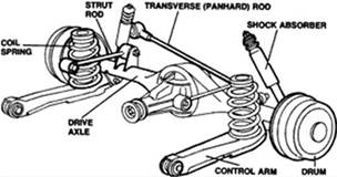
In the case of helical/cylinder springs with an independent rear suspension, a track bar or a Panhard bar is used. The vehicle or the chassis on the other side of the vehicle. Column connects Btrfait by axes of pivots that allow him to swing up and down only, so that the axis to move in the vertical level only. This does not affect the status of longitudinally axis but restrict lateral movement ( Latterl ), and this is used mostly with the arms of the trailing arms that work on the equilibrium axis in the longitudinal direction longitudinally. This combination is not normally used with leaf spring suspensions, as the springs themselves provide sufficient lateral stiffness, but are used only with cylinder spring suspensions.

 |
| The arms of the Trailing arms |
 |
 |
 |
| Bar / newspaper Bnhard Panhard bar |
Height / hump in the middle in front of the rear seat: One
of the attempts to reduce the car’s height and center of gravity is to lower the car’s floor. Cars in the front engine and rear traction there is a shaft located lengthwise in the middle of the car that needs a tunnel tunnel passes through, which shows a high part in the middle of the floor in front of the rear seats of the car. Cars with front engine and front wheel drive do not need a drive shaft for the rear wheels, and therefore there is no height in front of the rear seat. For trolleys, the chassis is high, so it does not need a shaft tunnel.
To lower the floor of the car, a space must be left between the floor and the shaft to allow for the oscillating movement of the shaft caused by the uneven ground and the loads and torques to which the axle is exposed. The solution procedure is to lower the axle, reduce its swing movement, and the other solution is to make a tunnel in the floor of the car (it appears as a raised front seat in front of the floor).
 |  | The car’s floor level is required to be lowered, which limits the amount of drop due to the presence of the steering column and its oscillation during rotation. To overcome this, the following modifications can be made to the column or to the car chassis, or both as follows: |
 | a) Shaft adjustment: 1) Motor shaft , gearbox and differential gears are tilted. Thus, the column goes down at opposite equal angles with the columns it is connected to. | |
 | 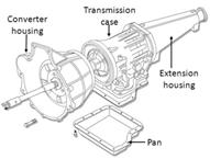 | 2) Extension of the empty gearbox, thus reducing the length of the shaft. In some cases the empty differential gearbox is extended. |
 |  | |
| One-piece i – shaft – with gearbox housing extension | One-piece shaft | ii – with an extension empty differential gears | |
 |  | 3) Dividing the shaft into two parts (two columns) reduces the working area of the shaft by reducing the moving part of the assembly. |
 |  | |
| Two-piece shaft with center-loading seat | Three-piece shaft (three drive shafts) with two middle bearings | |
 | b) Modification to the chassis: making a tunnel under the floor of the car through which the column passes. Which appears as a high / hump on the floor of the car in front of the rear seat in the middle. | |
 |  | C) The use of the front engine and front -engine traction , Front-wheel-drive (FF) This type of car finally gets rid of the drive shaft, where the engine and the driving wheels are on the front axle at the front of the car. |
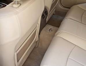 | 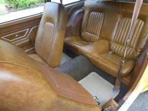 |
| The hump between the front of the rear seat is a tunnel in the floor of the car through which the power transmission shaft / driveshaft passes |
Bra safety shaft Prop-Shaft Strap :
Belt shaft or security loop safety scanner Loop , which is proving at the bottom of the chassis of the vehicle and passes the column through which, in the case of breaking column or public links damage to prevent the occurrence of the column and Angrach or dragging the ground while walking.
Shaft service: Universal joint service
lubricating the joints of many cars are factory lubricated . However, some construction equipment and automobiles with universal joints have a lubricating composition that must be lubricated periodically. Service for factory-lubricated general joints is limited to changing the joint in case there are indications/phenomena that there is excessive wear in the joint. Joints with lubricant are lubricated only with a low-pressure grease gun . Using a high pressure gun will damage the joint interlock, causing the joint to wear out quickly. There is also a slip yoke (joint) service that can be lubricated via the transmission or through a special lubrication joint .
Sliding shafts (1) shall be lubricated to reduce friction between sliding parts. Modern types of shafts have a layer of nylon lining on the sliding shafts . The shafts are lubricated during assembly and afterwards do not need lubrication as long as neither end of the tube and sleeve/casing are touched. There are 2 channels in the spider (the cross) to transfer the grease from the grease nipple to the needle bearings . Introduction of grease lubrication is (to link) through grease nipple (3) Grease Nipple .
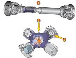 | 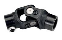 |
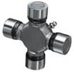 |
Adjust / Mahazh column:
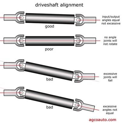
to allow changes in Mahazh / line – alignment and the distance distance between the leading components of driving components submissive driven for , shafts rotation often include one or more of the public links Universal Joints , links Jaw Jaw Couplings , or flexible joints Rag Joints , and sometimes link with courted splined joint or sliding link Prismatic Joint .
Poise column Shaft Balance :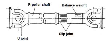
Angles Alamo d and Mahazh the Angle And Alignment :
Balance : Balance :
Balancing blocks rotary Balancing of rotating masses
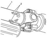
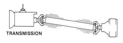
poise very important rotating objects to avoid vibrations Vibration . Vibrations can cause total breakdown, in addition to noise, and discomfort. It can be divided into static equilibrium and equilibrium with movement.
Balancing Static / Static Static balance
equilibrium static occurs when the center of gravity center of gravity of the body is located on the axis of rotation axis is Rotation Of . Thus, the body can remain stationary, and the axis is horizontal, without applying any brake force. It does not have any tendency to rotate as a result of gravitational forces.
Dynamic equilibrium Dynamic balance
is balanced rotor system in the event that the rotation does not produce any power centrifugal centrifugal force or duplication couple . The body rotates without the need to apply any external force or torque, which is not required to carry weight.
The rotating body may be dynamically unstable even though it is statically balanced in terms of weight distribution with respect to the axis, but the unbalance will generate counterclockwise centrifugal torque C d which must be resisted with clockwise torque F l = C d from the bearings.
Speed Critical Critical Speed :
Speed critical in the science of mechanics of solids solid mechanics is the rotational speed angular velocity theory that works to raise the natural frequency of natural frequency of rotating parts. Such as columns Shafts , columns and administration Propeller , or gears Gears , calf wheels. As the rotational speed increases and reaches the body’s natural frequency, the body begins to resonate , which causes the body’s vibration to increase dramatically. When the rotational speed reaches the value of the natural frequency of the body, this speed is called the critical speed.
All rotating shafts, even when there is no external load, will bend during rotation. The unbalanced mass of the rotating body will result in curvature which will result in resonant vibration At a certain speed, known as critical velocity. It is affected by many different factors. Vibrations increase dramatically when this speed is reached, and the speed before and after it is within reasonable limits. But when reaching that speed, even during exceeding it, it may take some time to be sufficient to cause damage to the body, and therefore the best solution is for the body not to reach that speed, and to make design and operational adjustments to prevent the body from reaching that speed.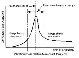
The crucial speed of the shaft is directly proportional to the shaft diameter (the greater the diameter the greater the value of the speed), and inversely proportional to the square of the length (the greater the length the lower the value of the speed). For this reason, the diameters are chosen as large as possible and the length as short as possible to keep the critical speed frequency of the shaft above the driving speed range. The shaft is longer than 1.5 meters between the common joints and causes unbalance problems. Shaft length is limited by using a blank (gear box and/or crankshaft case) with a longer span, and a common center coupling with two shafts.
The shaft is designed, the calculated critical speed should be 60% higher than the engine speed at maximum power.
Many have rear-wheel drive or four-wheel drive and require a long shaft between the gearbox and the rear axle.
1In this case, the distance is divided, and bearings are added to the column at the point of division loaded on a rubber base to absorb vibrations that may transfer to the car body. or done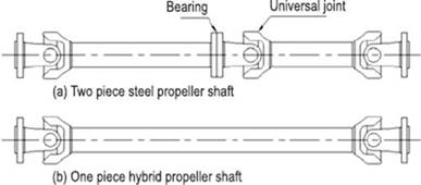
2 – Extending the empty gearbox or extended gearbox housing .
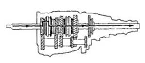
3 – Extended differential housing .
There are no reviews yet. Be the first one to write one.

