Injection system Electronic Electronic Fuel Injection System
are controlled process inoperationengine anddevices attachedit to reach the best performance by usingcontrol system inoperationengine (electronic injection system), which contain three main components are:
sensors ( SENSORS ):
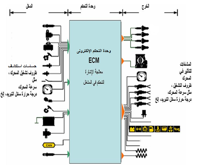
Itthat It captures physical values such as temperature, pressure, velocity, etc. and then sends electrical signals to the electronic control unit.
Electronic Control Unit ( ECU ):
which in turn performs a comparison process between the measured values of the sensors and the reference values stored inside it, and chooses the best values to send to the actuators in the form of electrical signals.
Starters ( ACTUATORS ):
It converts the electrical signals sent from the electronic control unit into mechanical quantities.
Engine control system subsections:

All of this must be controlled by the electronic control unit ( ECU ) in the engine. To achieve this, the engine is exploring the operating conditions by special devices known Balhassasat ( Sensors ). It explores, for example, engine speed, throttle opening, and more. We will talk in detail about the sensors in the next article.
The ECU processes the input information coming from the sensors and controls the output commands accordingly. The output devices are called actuators. The most important actuators are injectors and ignition coils, but there are a lot of actuators in the system. As for the output signals, it will be discussed in detail later.
The signal processing and output functions can be divided into six areas:
1- Fuel injection control.
2- Ignition control.
3- Controlling the idling speed.
4- Engine control.
5- Emission control.
6- Troubleshooting (breakdown security and support) and self-diagnostics.
The ECU uses stored functions and programs to process the input signals from the sensors. These signals are used as a base for calculating control signals for actuators (eg, ignition coils, injectors).
Engine control system subsections:

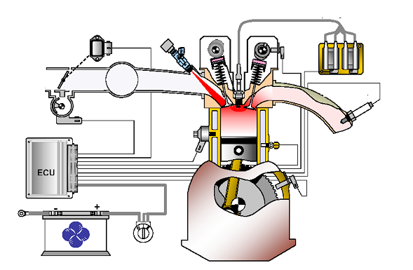
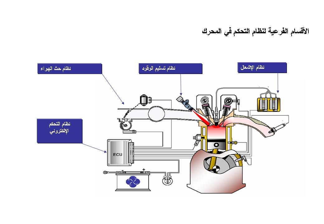
The modern electronic fuel injection system is divided into four basic sub-systems:
1- Air induction system.
2- Fuel delivery system.
3- Electronic ignition system.
4- Electronic control system.
And we will talk in this article about the air induction system.
air induction system:

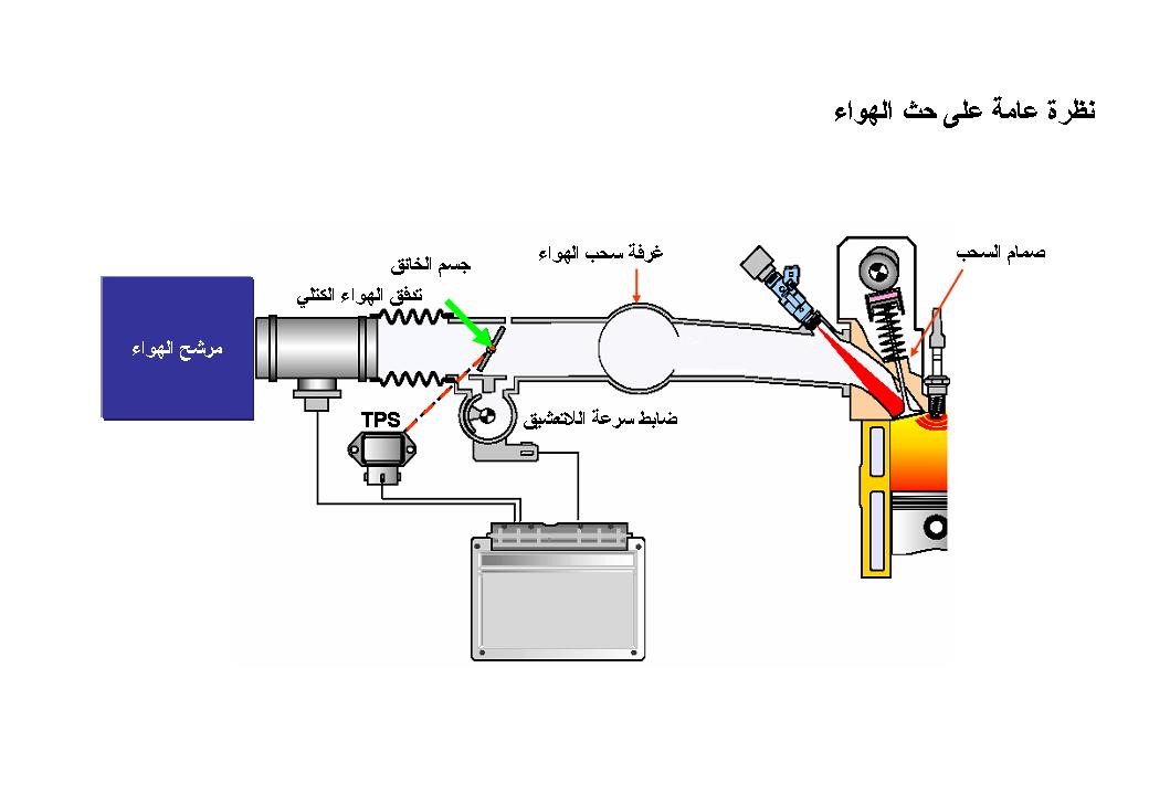
The induction system measures and controls the amount of air required for combustion. It mainly consists of:
1- Air purifier (filter). Air Filter
2- A sensor for measuring the amount of air (air flow meter). Mass Air Flow Sensor MAF
3- Throttle valve integrated into the throttle body. Throttle Position Sensor TPS
4- Air intake chamber (intake manifold). Intake Manifold
5- Intake valve. Intake Valve
When we open the throttle valve ( TPS ), air is sucked in by the piston (intake stroke) and flows through the air filter and air flow meter ( MAF).) through the throttle and intake manifold until it finally reaches the cylinder by passing through the intake valve. The air velocity is increased by the long, narrow intake manifold ducts, which improves the engine’s volumetric efficiency. The air entering the engine depends on the throttle opening angle and the engine speed. If the throttle opening is increased, more air will be allowed to enter the engine cylinders. The throttle position is detected by the throttle position sensor (TPS).
There are four different ways to measure intake air volume.
1- MAP Manifold Absolute Pressure Sensor .
And three different types of air flow meters: ( Mass Air Flow Sensor MAF )
1- Karman Vortex
2- The Hot Wire
3- Hot Film.
The idling control is installed to precisely control the idling speed and supply enough air to the closed throttle valve to provide a cool, fast idle under a certain engine temperature.
idle speed control
It is controlled Allatashiq speed (Alslaench) by the engine control unit through the control valve in Allatashiq speed ( the Idle ). The idle speed control system regulates the idle speed by adjusting the volume of air allowed to pass through the closed throttle valve.
This valve is located on the side of the gate, as at no-interlock speed the gate is closed, so the valve opens, allowing air to pass through an opening next to the gate.
Components of the idle speed control valve:

The valve assembly contains:
1- two solenoids T1, T2
2- permanent magnet.
3- valve.
4- Valve shaft.
The electronic control unit controls the valve movement using a 100 Hz actuating circuit for the coils T1 , T2 . Current flows in coil T1 when the operating signal is low, and in coil T2 . when the operating signal is lowWhen the signal is high. By changing the operating ratio, the magnetic field strength and position changes, which causes the valve shaft to rotate. A fail-safe bimetallic coil is attached to the shaft end to operate the valve in the event of a fault. When the engine is started, the idle speed control valve opens to a predetermined position depending on the coolant temperature and induced rev. Once the engine reaches a normal operating temperature, the engine speed gradually decreases.
It compares the value of the RPM real value of the RPM target / required to be corrected by the temperature of the engine whenever the temperature Zadeh less than the RPM through LED This is illustrated by the fault diagnosis device when entering on a Current Data as form:

One of the problems of the idle speed control valve is the difficulty of starting the engine.
Air Amount Sensor:
The air amount is measured in two ways:
The first method: Through the manifold absolute pressure sensor :
(MAP) Manifold Absolute Pressure Sensor
It is placed in the intake manifold and measures the amount of air as well as the air temperature and sends a signal to the electronic control unit, which in turn measures the amount of fuel required for injection.
The manifold absolute pressure ( MAP ) sensor detects pressure changes in the intake manifold caused by engine operating conditions such as engine speed and throttle opening.
The absolute collector pressure sensor consists of:
1- A pressure-resistant silicon wafer.
2- Integrated circuit (IC).
Vacuum is applied on one side and collector pressure is applied to the other. Due to this arrangement, a deflection occurs in the silicon wafer ( Diaphragm) and thus its resistance changes, and thus the output voltage changes. The amount of deflection depends only on the collector pressure. When the collector pressure changes, the resistance changes, and therefore the voltage changes. This change in resistance is then used to calculate the pressure in the accumulator, which finally allows the air intake to be calculated.
The absolute pressure sensor consists of four terminals:
1- Ground terminal.
2- 5 volt terminal.
3- Signal tip for calculating the amount of air.
4- Signal tip for calculating the air temperature.
In the event of a malfunction, it is detected through the fault diagnosis device, and it gives two readings as shown in the figure because, as we mentioned previously, it measures the amount of air and its temperature:
How to measure the MAP sensor :
Using the multimeter, the electrical terminal is measured and must be given 5 volts (Fig. A), then the ground measurement must be given and zero volts must be given (Fig. B). After ensuring the safety of these parties, the signal is measured through a fault diagnosis device from the Current Data mode, and the value of pressure and voltage is noted (Fig. C).
Ground Party Ground – of Signal tip signal – Sensor the Power Party Power

The second method – through the air mass sensor:
( Intake Air Temperature Sensor IATS ) .
This sensor is placed between the air filter and the gate body, and it measures the amount of air as well as its temperature.
There are two types of it:
1- Karman Vortex air intake sensor :
it relies on generating vortices as the number of these vortices is proportional to the volume of air flowing. The higher the air flow, the more vortices are generated. The amount of eddies and thus the amount of air is measured.
2. Sensitive measuring the amount of air -type hot wire / hot membrane ( . Hot Film ):
To obtain greater accuracy when measuring, mass air flow sensors have been developed, which measure the mass of intake air. The main part for measuring mass is the hot wire or in later versions the hot membrane. The hot wire is kept at a constant temperature by an electronic control circuit. Any increase in air flow causes the wire to lose heat faster, which is compensated by sending additional current through the wire. This current is measured and an output signal proportional to it is sent to the engine control unit from which the air intake can be known. The hot film type uses the same principle.
The MAF air intake sensor consists of 5 terminals:
1- Ground terminal.
2- The 12 volt terminal.
3- Indication tip for the amount of air.
4- 5 volt terminal.
5- Air temperature indication tip.
In the event of a malfunction, it is detected by the fault diagnosis device, as shown in the figure:

Note: The sensor for measuring the amount of air in the engine is either the engine contains an absolute pressure sensor ( MAP ) or a measurement sensor for the mass of air flow ( MAF ), and the two do not combine in one engine.
Malfunctions that occur if this sensor malfunctions:
1- The engine will start normally, but it will rotate poorly and may stop suddenly in non-clutch conditions. A diagnostic trouble code may not be assigned if this problem occurs.
In the event of a malfunction in the intake air temperature sensor, or it generates a wrong output, the engine may show the following symptoms:
1- Weak acceleration (it doesn’t pull).
2- The ignition timing may not be corrected and may lead to knocking and increased fuel consumption.
Put the throttle ( a sensitive Throttle Sensor By Position the TPS ):
Sensor is placed put the throttle in the body of the gorge where the body throttle consists of a throttle circle stream Allatashiq air and sensitive position of the throttle also includes a variety of outlets from vacuum sources to run, for example , devices to reduce emissions such as recycling valve exhaust gas ..
The sensitive mode throttle select Portal mode.
This sensor is a potentiometer (a potentiometer) to measure the exact opening of the gate. The electronic control unit calculates the amount of air entering the gate by determining the angle of opening the gate and the speed of the motor. Opening the gate and depending on the signal, the angle varies.
In the event of a malfunction, it is detected by the fault diagnosis device, as shown in the figure:
The throttle position sensor has three terminals:
1- Ground terminal.
2- 5 volt terminal.
3- Signal party.
A type contains the gate sensor and the Idle as one group.
To test the sensor terminals:
The resistance is measured between each terminal as shown in the figure:

Thus, we have finished the air intake system and its sensors.
There are no reviews yet. Be the first one to write one.

