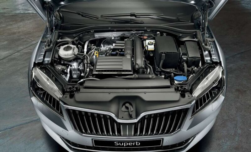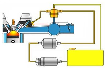
Fuel delivery (injection) system in the electronic injection system
Introduction:
We have already talked in a previous article about the sub-systems in the electronic injection system in modern cars, and we have clarified that there are four sub-systems, namely:
1- Air induction system.
2- Fuel (injection) delivery system.
3- Electronic ignition system.
4- Electronic control system.
In this article, we will talk about the second system of electronic injection subsystems, which is the fuel delivery (injection) system.
Components of a fuel injection (delivery) system in electronic injection systems: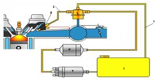
The fuel delivery system consists of
1- fuel tank. Fuel Tank
2- The fuel pump. Fuel Pump
3- Fuel filter. Fuel Filter
4- Fuel delivery tube. Fuel Rail
5- The fuel injector. Injector
6- Fuel pressure regulator. Fuel Regulator
7- Fuel return tube. Fuel Return Pipe
Fuel is delivered from the reservoir to the injector ( Injector ) by Electric Fuel Pump ( fuel Pump) that is located in or directly next to the fuel tank. The pollutants are filtered by a high capacity fuel filter. In most systems to date, the fuel pressure is kept constant and connected to the accumulator pressure by the pressure regulator, in order to keep the injection amount at the correct level according to when the injector is opened. Excess fuel is returned to the tank.
Fuel Pump Fuel Pump :
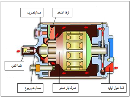
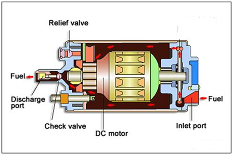
The fuel pumps that are installed inside the tank are characterized by low operating noise, to reduce the fuel discharge pulsation, and they have great features to prevent fuel leakage and vapor retention.
These pumps are called wet pumps as the electric motor runs while it is submerged in fuel. The passage of fuel through the pump motor helps in the cooling and lubrication of the internal pump parts.
The pump has a built-in Relief Valve in case of supply line clogging. This valve opens if the fuel pressure exceeds the specified value, to return the high pressure fuel to the pump inlet side.
There are LED Allardjaa Check Valve , which will close the outlet when the pump stops. This maintains the pressure level in the fuel line to prevent vapor retention. This in turn ensures a better start the next time (starting the engine again).
A fuel filterFuel Filter is installed in the fuel supply line to prevent dirt from entering and damaging or blocking the injectors. And if the filter becomes obstructed to the flow of fuel, the engine will suffer from aging, power loss under load, and hard starting problems. Although it is rare for clogged filters to be completely replaced, this can happen, for example, due to poor fuel quality, in which case the engine will not be able to start. Therefore, the fuel filter must be serviced periodically.
During filter replacement, attention should be paid to the correct orientation of the filter installation, as most filters have a specific direction of flow. Where it is not installed correctly, it prevents fuel from reaching the injectors, and this happens a lot when we change the filter, we notice that the fuel does not reach the engine, and some consider that the problem is in the pump, and therefore it is necessary to make sure that the fuel filter is installed in the pump in the correct direction when changing it.
How the fuel pump works:
The operation of the pump is controlled by a special pump relay located in the fuse box, and the fuel pump is operated by a signal from the car’s electronic control unit. Where this signal is sent after receiving a signal from the CKP Crank Shaft Position Sensor by the engine control unit, which in turn opens the pump relay and connects the electrical circuit, then the battery delivers electricity to the pump.
Methods of testing the fuel pump:
There are three methods for testing the pump:
1- Checking the connections.
2- Operating voltage test.
3- Check the fuel pressure.
The following is how the tests work:
Connect the battery positive to the pump terminal of the pump positive and note the buzzing sound from the pump or remove the fuel delivery hose of the engine and watch the fuel exit from it.
To measure the operating voltage of the pump, the voltage at the pump terminals is measured with the engine running. The voltage value of the battery must be the same as the battery voltage (about 12.8 volts). If the voltage value is not the same as the battery voltage, the fuse, pump relay, electrical connections or the control unit itself will be detected.
To test the pressure, this is by measuring the pressure by referring to the service manual. We can also dismantle the fuel line connecting to the injectors and the engine management and observe the shape and pressure of the fuel when it is outside the sprinkler with the naked eye.
In some engines, there is an Auto Fuel Cut Sensor, and its function is to cut off the fuel supply in the event of a car collision so that a fire does not occur.

How the Auto Fuel Cut Sensor works : It
is a metal ball (steel) placed at the bottom on a small V -shaped sheet andworks by magnetic force. When a collision occurs, the ball moves up and opens the circuit of the fuel pump, so the pump stops working.
Delivery Pipe and Pressure Regulator:
To date, most fuel delivery systems are classified as retrograde fuel delivery systems. In these systems are regulated byfuel pressure regulator Pressure Regulator Pressure in relationpressurecomplex. Excess fuel is returned to the tank. The pressurized fuel delivered by the pump flows from the filter to the fuel rail . Where the fuel delivery tube acts as a tank.
There are two pressure regulator systems:
1- A system in which the pressure regulator is installed at the end of the delivery pipe.
2- A system in which the pressure regulator is installed with the fuel pump.
The Regulator Pressure installed on the tip of the Rail tube maintains the pressure in the rod at a specified value above the intake manifold pressure in order to provide an effective and stable injection pressure. The amount of injection depends mainly on the pressure, the time of injection, and the size of the injector nozzle. Since the orifice size and pressure are kept constant relative to the accumulator pressure, the amount of fuel injected can be precisely controlled by the ECM by varying the opening time of the injector. Excess fuel is returned to the tank via the fuel return line and the basic setup of the fuel pressure regulator is made based on atmospheric pressure, the pressure being maintained at 3.35 bar. This can be achieved by closing the return line to the tank with a spring-loaded valve, which opens the return line only if the pressure is above 3.35 bar.
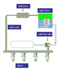
– Return fuel system (pressure regulator mounted on the pump): The
newer models of injection systems are non-return fuel systems (RLFS), without a return line to the fuel tank. The purpose is not only to reduce fuel vapor from the return line but also to avoid higher evaporation as the fuel returning from the regulator increases the fuel temperature in the tank and thus also the amount of steam. The system has been developed based on improved fuel vapor regulations. Now the fuel regulator is installed on the fuel pump unit and set to a constant value (3.8 bar).

Note: The fuel pressure regulator is actuator and not sensitive.
Injector Injector :
Injector of valve actuators , a measure on the subject of cloud complex can be controlled by the engine control unit. Injectors are mainly composed of injector housing, injector nozzle and solenoid. The nozzle opens and closes in response to the solenoid, which is in turn activated and deactivated by the ECM. There are two common types of actuator circuits currently used in motors. Both actuators operate on the principle of ground control, but one uses an external solenoid resistor and a low-impedance injector (0.6 to 3 ohms), and the other uses a high-impedance injector (12 to 17 ohms) without a separate resistor.
The injector also requires the following criteria to be met:
1- An accurate fuel flow rate.
2- Good straightening.
3- Wide effective range.
4- Good spray features.
5- No leakage, low noise and durability.
It offers many different types to suit the different needs of all engines. An example is the different amount of spray nozzles and the different shapes of spray models.
Injector test methods:
1- Resistance test.
2- Test the playback sound.
3- Test with a test lamp.
4- Test the shape of the signal.
5- Injection test.
6- Test by Current Data by fault diagnosis device.
To test the resistance, disconnect the injector plug and measure the resistance between the two ends of the injector.

To test the operating sound, the head of the screwdriver is placed on the injector, the ear is placed on the base of the screwdriver, and the sound of the injector operating (the needle pulse) is heard.

To test the operation of the injector using the test bulb, the end of the bulb wire is connected to the positive terminal of the battery, and the other end of the bulb is connected to the end of the wire coming from the control unit, and we notice whether the test bulb is lit or not.

To test the injection, the injectors are removed from the engine and placed on the injector test device, the injectors are turned on, and the injection shape and the amount of injected fuel are observed inside the test tubes.

Testing with a fault diagnosis device:
1- The injectors can be tested by entering the Actuation Test menu , through which it is possible to know whether the injector is working or not.
2. Through the list of Current Data and note for injection Injection Duration with engine speed Engine , the Speed .

There are no reviews yet. Be the first one to write one.

